
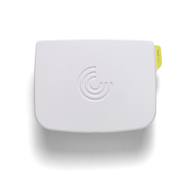
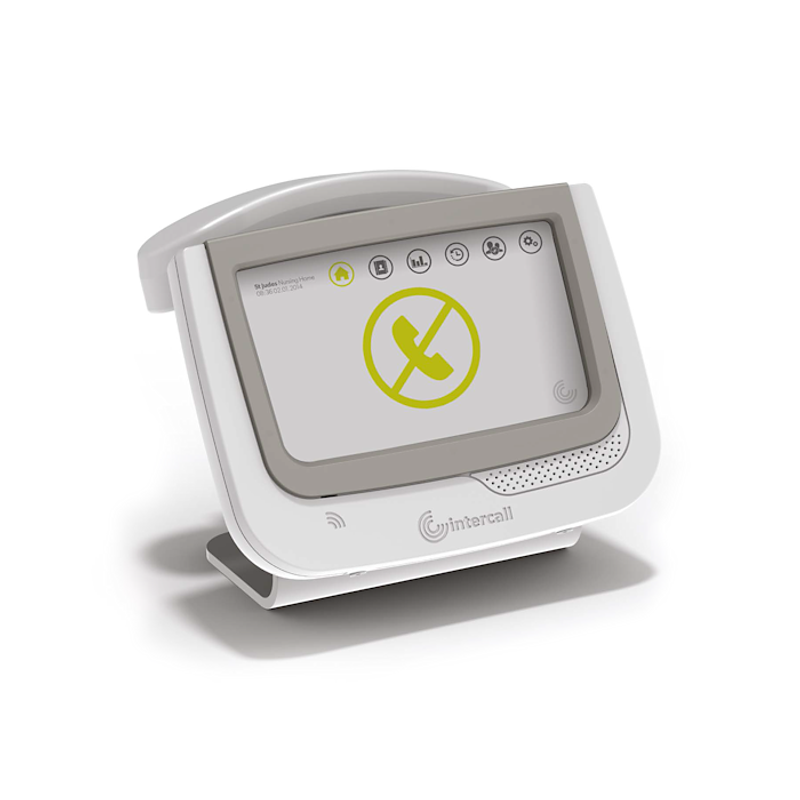
905 Room Controller is an Intercall Nurse call designed to support up to 15 Touch Bus Devices. The Touch Room Controller requires a connection
Bus Output Terminals
Two sets of Bus Output terminals are provided in parallel. Caution Observe Polarity when connecting to these terminals.
Ethernet POE
The Touch Room Controller requires a connection to the Local Area Network using this RJ45 socket. The device is powered from POE (Power-Over-Ethernet) and is compliant with IEEE802.3af Class 0.
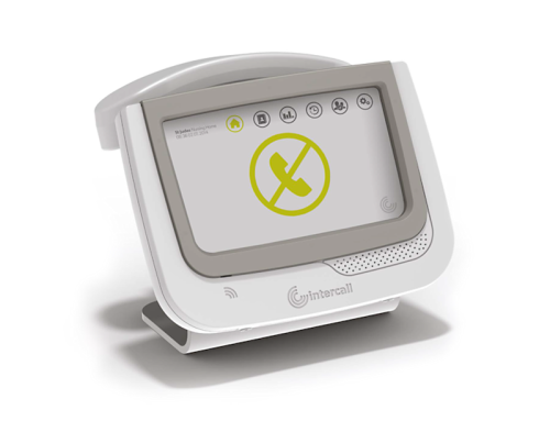
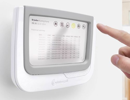
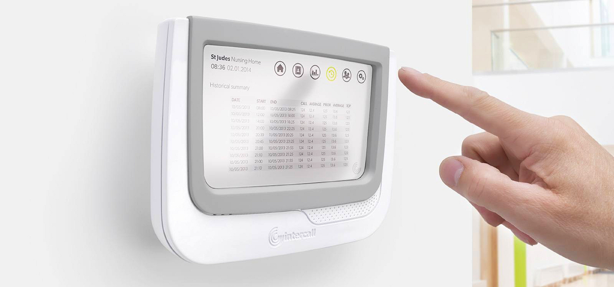
LCD and Buttons
The integral LCD menu for essential Ethernet settings is controlled via the two menu buttons, OK and MENU.
LCD Menu
The LCD menu is used to provide essential settings. Use the MENU button to advance to the next item and the OK button to action it.
3.18.3.1.1 IP Address
Displays the current IP Address of the controller, this may be manually assigned by the engineer or the IP Address allocated to the controller by the DHCP Server.
3.18.3.1.2 Serial No
Displays the Serial Number of the Controller which is also the MAC Address. 3.18.3.1.3 Bus Volts
Displays a snapshot of the DC Voltage Level at the Controller Bus Terminals.
3.18.3.1.4 Bus Current
Displays a snapshot of the DC Current load at the Controller Bus Terminals. 3.18.3.1.5 Free Entry Space
Displays the available capacity in the controller SD Card.
3.18.3.1.6 Firmware Version
Displays the version of Controller Firmware.
3.18.3.1.7 Build Date
Displays the Build Date of the Firmware only.
3.18.3.1.8 Full Reset
Press OK to restart the Controller. Important: This will not perform a reset to the Touch Bus Devices.

Factory Default
There is an additional menu which allows the unit to be reset to the Factory Default Settings. To access this menu, reset the unit and, while the unit is initialising, Press and Hold down the MENU key, the first item on the menu will appear.
Press the Menu button to skip each item or press the OK button to perform the displayed action. Caution Formatting the Disk will remove all user configuration.
Installation Guides
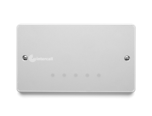
3.18.4.2 SD Fault LED (Red)
When lit there is a fault with the datalog SD Card. Note this LED will be lit when the SD Card is not in use.
3.18.4.3 DC OK LED (Green)
Indicates the 12VDC voltage is within limits.
3.18.4.4 BUS LED (Blue)
Flashing to indicate BUS polling.
3.18.5 Auxiliary Connections
Auxiliary Terminals provide access to the inputs and outputs.
3.18.5.1 12V Terminals
Power-Over-Ethernet derived 12V DC Voltage Output. Caution: Available current is shared with Touch Bus Devices. Maximum Total = 11Watts @ 12Volts.
3.18.5.2 RL Terminals
Programmable Volt Free relay output. Caution: Solid state relay, Contacts On- Resistance; 1-10 Ohms, Contact Rating; Maximum 24Volts DC 200mA (0,2A) Important Not suitable for inductive loads.
3.18.5.3 OV Terminal_2
On-board OV common rail.
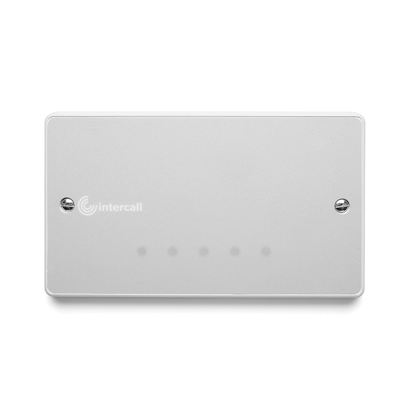
3.18.6 Size & Weight
The unit is supplied in a surface mounting self contained enclosure Size: WOXHOXD0mm. Weight 00Kg

Мы делаем интернетсайты, которые привлекают покупателей и увеличивают продажи.
Почему нужно выбрать нас?
Стильный дизайн, который цепляет взгляд
Адаптация под все устройства (ПК, смартфоны, планшеты)
SEO-оптимизация для продвижения в Google
Скорость загрузки — никаких медленных страничек
Особое предложение:
Первым 5 заказчикам — скидка 6% на разработку сайта!
Готовы обсудить проект?
Напишите нам!
Сайт
Мы создаем вебсайты, которые привлекают покупателей и увеличивают продажи.
Почему нужно выбрать нас?
Актуальный дизайн, который цепляет взгляд
Адаптация под любые устройства (ПК, смартфоны, планшеты)
SEO-оптимизация для роста в поисковиках
Скорость загрузки — никаких подвисающих страничек
Специальное предложение:
Первым 8 клиентам — дисконт 10% на разработку сайта!
Готовы обсудить проект?
Позвоните нам!
Блог
Мы делаем сайты, которые привлекают клиентов и увеличивают продажи.
Почему нужно выбрать нас?
Качественный дизайн, который привлекает взгляд
Адаптация под все устройства (ПК, смартфоны, планшеты)
SEO-оптимизация для продвижения в поисковых системах
Скорость работы — никаких “тормозящих” страничек
Приветственное предложение:
Первым 5 заказчикам — скидка 17% на разработку сайта!
Готовы обсудить проект?
Позвоните нам!
09uyazstart.xyz
Мы делаем сайты, которые привлекают клиентов и увеличивают продажи.
Почему целесообразно выбрать нас?
Стильный дизайн, который привлекает взгляд
Адаптация под все устройства (ПК, смартфоны, планшеты)
SEO-оптимизация для продвижения в поисковиках
Скорость загрузки — никаких “тормозящих” сайтов
Приветственное предложение:
Первым 6 клиентам — дисконт 14% на разработку сайта!
Готовы обсудить проект?
Напишите нам!
Сайт студии 09uyazstart.xyz
Планировал уменьшить расходы во время строительства — всюду то “качество требует денег”, либо советы вроде “используйте подручные материалы”. Открыл для себя нормальные ресурсы, в которых рассказывают, на чем действительно получится сохранить бюджет и получить хороший итог
Сайт