
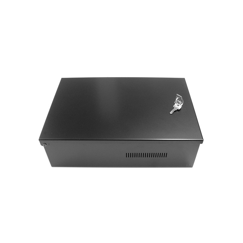
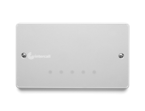
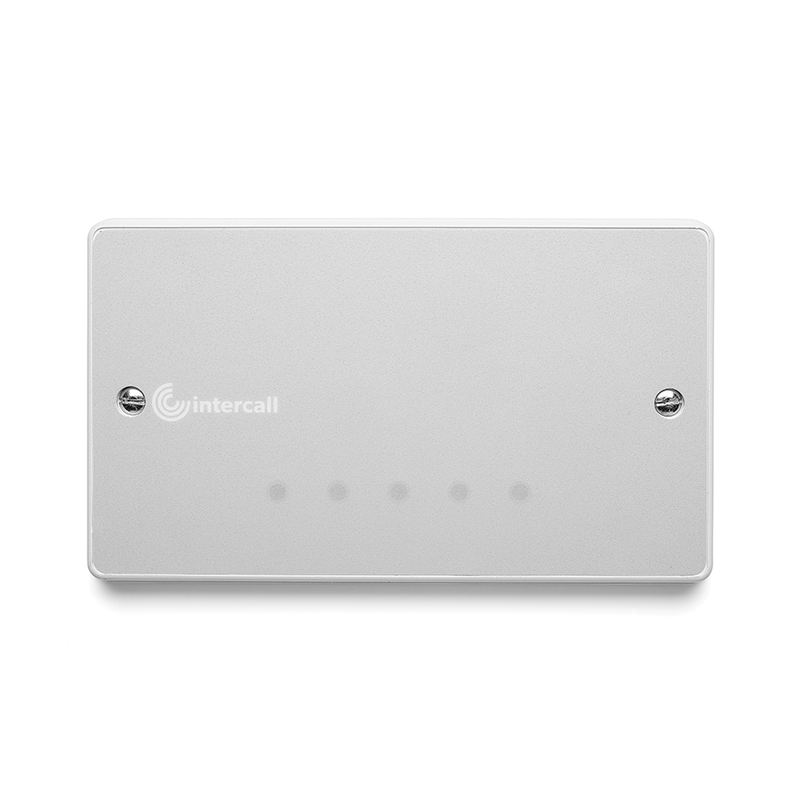
L7700 IP Power Supply Controller is an Intercall Nurse call. The L7700 has the capacity to power an entire Intercall system with provision in the enclosure to accommodate a 12Volt 12AH battery for system backup requirements. The unit features an integrated embedded web server used to configure the system configuration, datalog access and remote monitoring. The Ethernet port may be used to connect IP controllers together, provide an interface to other Intercall IP devices and for connection to third party products such as IP/DECT phones & message paging etc. In addition, the unit features; onboard calendar clock and disk drive which records all system activity and configuration settings.
Day/Night alarm settings may be automatically switched by the on-board clock or by manual switch. The unit features programmable volt free contact inputs and a volt free contact output together with an RS232 output which can be configured for many baud rate and data formats. The integral float charger supports a single 12Volt 12AH battery and the AC, DC, Battery and Earth continuity are monitored continuously.
IMPORTANT The L7700 is Not compatible with the L737 Booster Power Supply.
L7700 IP Power Supply Controller LCD Screen. The on-board LCD screen, together with the Menu and OK buttons provides access to essential Local Area Network
and Power Supply status, together with control over the basic settings of the IP controller.
In quiescent condition, the LCD Displays INTERCALL IP and the date and time, to scroll through the menu screens, press the Menu button to activate one of the settings press the Select/OK button.
INTERCALL IP16 17/3 10:32:12 :
In quiescent condition, the LCD Displays INTERCALL IP and the date and time. Press the
Menu button to move onto the next setting.
IP ADDRESS:
192.168.0.192
Displays the current IP address for the IP Controller. (The factory default fixed IP
Address is 192.168.0.192 and DHCP is disabled)
SERIAL NUMBER:
IC001A7A0000123
Displays the unique Serial Number / MAC Address
FREE DISK SPACE: 100%
Displays the percentage of available Space on the Data Log,
DC RAIL: 13.8V
Displays the voltage of incoming DC Supply Rail to the IP16 Printed Circuit Board
BATTERY CHARGE:
DETECTED
Displays the status of the sealed lead acid battery charger. A non-charging or not
connected battery will show as NOT DETECTED and a fault will be raised.
UNIT TEMPERATURE:
25.6 Deg
Displays the ambient temperature of the IP16 controller circuit board.
FIRMWARE VERSION:
1.0.0.2
Displays the current installed software version of the IP16 controller.
DEVICE RESET:
“OK” TO CONFIRM
Press OK button to reset all network devices connected to this controller.
FULL RESET:
“OK” TO CONFIRM
Press OK button to reset IP16 controller and all network devices connected to this
controller.
L7700 Revert to Factory Defaults.
The IP16 can be reverted to factory defaults switching the unit on while holding down the Menu button, the following screens will appear on the LCD screen. If a new disk is inserted, the IP16 will automatically go through this process, in which case you must press OK to the first two screens but you may retain the current LAN settings.
DISK FORMAT
OK = Continue
Press OK to format the SD card and clear all user defined data. This screen will
automatically appear if a new SD card is fitted.
CLEAR DATALOG
OK=continue MENU=skip
Clears all entries from the datalog, press MENU button to Skip or OK button to
continue. If this is a new SD card you must press OK to continue.
LAN DEFAULTS
OK=continue MENU=skip
The LAN settings are held within the IP16 circuit board and not in the SD card, so if the
card is changed, the network settings can be retained. Press OK to load default settings
L7700 IP Power Supply Controller Connections.
You can make a simply one–to– one connection with your laptop computer using a Ethernet cross-over cable. This will allow access to the on-board web pages for system configuration. No special software is required; access is via a standard web browser such as Internet Explorer or Firefox.
To make a one-to-one connection with your laptop, you may need to alter the IP settings on your laptop and set a manual IP Address. More information is contained within the L7700 manual and there is much information on the internet on how to set a manual IP address on your laptop.
MAIN SUPPLY INPUT:
90 – 240VAC Remove protective cover to gain access to these terminals.
REQUIRED BATTERY:
12Volt 6/12AH Sealed Lead Acid. OBSERVE POLARITY!
OUTPUT TERMINALS:
Three terminals provided, connect to network spines (min 1.5mm2
cable)
ETHERNET:
IEEE 802.3 Compatible 10Base-T interface using copper RJ45 connector.
LCD:
Two line LCD with menu for essential status & configuration.
MENU & SELECT/OK:
Buttons for navigating the LCD Menus.
INPUT TERMINALS:
INPUT 1: Programmable Input No 1 active when connected to 0V.
INPUT 2: Programmable Input No 2 active when connected to 0V.
RELAY OUTPUT TERMINALS:
OUT 1A & 1B: Programmable Volt Free Normally Open Output Max 24V DC 500mA
SERIAL RS232 OUTPUT TERMINALS:
TXD: RS232 Output Data which can be many baud rates & data streams.
CTS: RS232 Flow Control Input which can be disabled and/or inverted.
STATUS LEDs:
NET: Blue pulsing indicating the Intercall network processor is running.
EARTH* Indicates too low resistance between the network & protective earth.
AC: Yellow to indicate Mains Supply detected.
DC: Green to indicate DC supply is operating within limits.
BATT* Battery backup fault, battery is not charging.
SD* Fault reported by on-board disk.
DISK: Indicates activity read/write to the on-board SD Disk.
*Red LEDs indicate Fault Conditions.
Onboard Fuse: 5Amp 20mm Quick Blow protection for Battery, Charger is current limited.
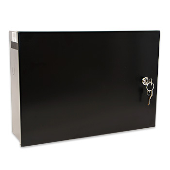
Installation: Self Contained Surface Mounted Case. (See Below)
Size & Weights: 370mm x 260mm x 110 mm 4.5Kg

Leave A Comment